Friday, April 10, 2015

Beginning work on the Utility Arm Motorization kit

This week, I started work on the Utility Arm Motorization Kit, offered by Rotopod on the Astromech forums.  


The kit is very complete and his step by step instructions on the forum are pretty much spot on.  I did run across a few stumbles, which I hope this blog with clarify for other builders getting ready to put theirs together!

The structure that holds the arms is called the "Utility Arm Carrier" and consists of the side pieces and horizontal ones.  The arms are held in place in there with a shaft, secured with spacers that sit in shallow holes in the horizontal pieces.  

With this kit, those spacers are replaced with pulleys and belts, driven by servo motors.  

First the horizontal pieces need to have the holes widened   The recess will stay but the hole needs to have a 3/8 inch drill bit widen the hole.  The allows for the bearing to fit inside.


I used an R2-D2 toy as a reference, so I would recall where the pivot point was for each arm.  For example, the top one pivots opposite the bottom.  I even labeled the horizontal pieces so I would know which was which.  In the picture, I have "Bot Top" and "BB" (Bottom Bottom) to indicate they are for the lower arm.  On the left you can see "TT" (Top Top) and TB (Top Bottom) written on the pieces.  While not necessary, I did it to help maintain order.

Now on to the Utility Arms, which I recently cleaned up and beadblast the Dykem off of.  

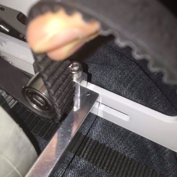
First, a hole has to be drilled, then tapped, so that a set screw can thread in and ensure a tight fit for the pivot shaft.  The set screw is 6/32 so the hole will be pretty tiny!  With the utility arm being curved, I will have to use the hand drill and vice to drill the hole.

I use the hole punch tool so that I have a divot to drill into.  This prevents the drill tip from wandering.  Even more important since the area we are drilling is curved and we need a good, straight hole into the pivot hole.


Now on to the pivot shafts.  

Mine went on extremely tight, I didn't need to sand them...but I did use the vice so I could lightly tap the shaft into place, making sure the flat side faces where the set screw will be.


Once they are in, you need to find an extremely tiny metric allen wrench for the set screws to be screwed into position.  

Then, on to the pulleys.  I put the wrong ones on (as you will see in the next few photos), so be sure you are putting these on....

These go on the Utility Arms!  The other cogs will go to the motor
And (again wrong pulley in the picture), you line the set screw to flat side of the pivot shift to secure it.  Each pulley has two holes for set screws, I put one in each.  I also used a mini vice and a small hammer to center the shaft as needed before tightening the set screws


Now, time to piece together the Utility Arm Carrier while adding some new mounting pieces.

I found by putting the top and bottom pieces on, then loosely attaching the back plate worked best.  You'll find you need to really squeeze the back plate at times to get holes to line up.

Notice the widened hole on the lower left, which, looking at the R2 statue, matches where the pivot piece is
Next, the frame mounting brackets go on.  As a reference, this picture from Rotopod's instructions reminds you which one is mounted higher than the other.


To attach the mounting brackets, you wind up doing some delicate swapping around of the machine screws.  What was holding a piece on gets removed, then put back on with the mounting bracket.


Now its time to see how well the utility arms fit.  Shims are included, as needed...and many had to sand theirs down considerably.  With them in, I couldn't screw the horizontal piece back in.  Too thick, need to sand them down thinner.

Note on the right, the holes are showing, meaning the spacers are too thick.  Thinner spacers will move the horizontal support up a bit, allowing it to be bolted back together


I sanded and sanded...but was still not working out.


...so I decided to improvise and drill 0.25 inch holes in some plastic packaging, cut it out into the shape of the shims and install.


...and everything fits.  I am able to screw everything back together and the arms move freely with so friction/rubbing.  Furthermore, the arms are straight and not sagging.


Right now, I am awaiting the arrival of the servo motors for the next few steps...more in a day or two!


Wednesday, April 1, 2015

New Foot drives!

Over the last few nights, I have been assembling the NEW foot drives for R2.

Back in 2011, I had purchased a JAG foot drive for this droid, identical to what is in my first droid.  That drive system takes the output from the motor, gears it down via a belt drive to the wheel.  The housing fits perfectly in the foot shell and the drive system uses a motor that is extremely easy to acquire.  Where this is using one drive wheel, a caster wheel is used to keep R2 level.

Original JAG Foot drives
A couple of years ago, a fellow R2 Builder was looking for some foot drives to complete their R2 build.  Since my build had quite a few years to go, I sold these to him and figured I could purchase a replacement in the future.

Fast forward to 2013 and Jerry Greene has improved his design, now featuring "four wheel drive".  Meaning, the 2 wheels in each foot will be powered, no more dragging a caster wheel inside.  Those have been problematic for me, sometimes causing R2 to get stuck trying to cross uneven surfaces.

When Jerry first posted pictures of the prototype, many of us were interested!


The benefits of this drive kit over the previous one is simple:  More power!  Better ability to cross uneven surfaces, since both wheels are powered and no caster wheel causing issues binding or not being level.

And...it makes having R2 in 2-leg mode a bit easier.  R2 will be level, standing on 4 identical tires!

The kit has a fair amount of parts but between the exploded-view drawing Jerry includes and pictures of a step-by-step assembly, it goes together fairly smoothly.

There certainly are some tight spots to deal with, such as maneuvering a wrench around four closely spaced hex heads!

Some tight spots for tools!
 With the help of my loyal, 15-year old cat, Mokey, we slowly assembled the foot drives.  

Laptop showing the assembly photos while Mokey supervises


This is all a test fit for the most part, since some dis-assembly will be required later.  Later, I will need to drill holes in the foot shells to mount the assembly into it.

On to the assembly...


The belt pulley mount was an interesting challenge.  The housing makes getting the allen wrench in there a bit tricky!  Then, once you have the pulley mounted and the belt tight, you can't help but notice how tight the clearance is.  While hard to see in this photo, the belt comes close to the adjustable wheel mount (shiny piece).  It looks good, I don't think it will rub.


The finished drive kits!


In a few weeks I hope to have the motors on hand to complete the fit test.  I want to make sure the belt will work out alright.

Once that is completed, then the next step will be the installation into the foot shell!

Thanks for reading....progress continues!

Friday, March 20, 2015

Back at it...utility arm clean up!

It has been several months since I last posted any blog updates on my R2 build! 

My last update was in July and since then, I lost my job, was unemployed for a few weeks, picked up a part-time job, took all the hours they would give me, and then found a new full-time job!  

During those weeks of unemployment and under-employment, I just didn't have the motivation to work on my droid.  Funds were tight, so the last thing I wanted to do was work on the droid, then discover I needed parts I couldn't afford.  Why deepen the depression, right?  

Now, I am working full-time and I also kept the part-time job as well.  I'm making ends meet and trying to replenish the savings account while also having a modest droid building budget!

That said...here's what I have been up to...

Last time, I was back tracking on the Dykem metal dye, using acetone to clean it off the utility arms.  One problem was some areas of the arms still had the dye.  I really wanted to remove more than the acetone did.  The cut outs that reduce weight were still quite blue inside.  

Utility Arms have cut outs milled to lighten them.

Leftover metal dye that the acetone bath didn't melt away

The arms are very shiny and I wanted to bead blast them anyways.  This would help remove more of the dye and roughen the surface up some.  That would be great for when it is time to prime and paint them.  (With what paint formula remains to be decided!)

My pal, Fred, picked up an inexpensive bead blaster from Harbor Freight a year ago.  And as you would expect from such a bargain price, it was pretty finicky to work with.  Using 80 grit glass beads, it would work well for a few minutes, clog (spit only air), require some gentle prodding and then resume work for a couple minutes.  

Harbor Freight bead blaster and Utility Arm
After 45 minutes of work, I was satisfied I had done as much as I could.


Next time, I will start assembling the Utility Arm mechanization kit that a fellow R2 Builder developed last year.  It looks very cleverly designed and I am anxious to start on it!

Wednesday, July 30, 2014

Time to re-think R2-D2 Blue!

Back in 2012, many of us R2 Builders thought we had found the perfect blue!  We stumbled onto Dykem, a metal dye that was used on the original R2-D2s in STAR WARS A New Hope.  It appears the crew were doing a fair amount of touch ups during filming since the Dykem blue goes to all purple after a while, so to stay blue, frequent touch ups and re-do's are needed.

We thought we had it nailed down to a decent formula.  Polish the aluminum pieces (plastic pieces need a shiny silver base coat), apply the Dykem, apply a coat of DupliColor Metalcast Blue Anodized and a few coats of a UV clear coat.  However getting Dykem to go on well was a challenge with my airbrush.  Then, there was how those purplish-blue pieces look a year later.  Based on pictures other builders posted, it was an eventual failure.  

I painted several of the pieces in my 2012 post.  Any some of the pieces came out really good, despite a very laborious process.  However, close to two years later, the color has changed.  Now that I have a new 300 mm dome ready to be un-boxed, prepped and painted, its very important all the "blue paint" matches!

Currently I am testing some formulas/recipes that other builders have used and are pleased with.  Some are rattle-can formulas, as I used on the first R2.  The blue I have on the first R2-D2 is what we call "Krider Blue", but the Rustoleum Metallic Purple has been discontinued.  I'll post pictures of the tests later on!

That said, today was all about removing the paint.  I figured out a low tech way to do this...used two paint roller trays and an old paint brush.  I filled one with water and the other I filled with enough acetone to work the part around in.  (SAFETY REMINDER - I did this outdoors with plenty of ventilation, eye protection and gloves!)


In went the utility arms and using the paint brush, I just kept slowly applying acetone to the part.  The paint and dye quickly started to peel off the part.  So much so that it was clogging the brush bristles and the acetone was full of chunks of paint.  After the part was pretty much free of paint, into the water it went.


Now my method is hardly the best, in hindsight.  I wound up using a cloth with acetone on it it to wipe off those stubborn specks.  The resin eye is going to take some more work since the silver base-coat will require some light sanding to completely remove all the paint and primer.

The aluminum arms have cut outs to make them lighter, which also means you can still see paint in side those holes.  Those will require a bit more labor to be completely free of paint and dye!


Many more parts to remove paint from!

Next up will be modifying the aluminum utility arms so they can travel in and out of the body skins.  More soon....


Wednesday, February 19, 2014

Lifter mechanism motor work

Work continues on the lifter mechanism!

The challenge this time is the motor shaft to gear connection.

The original design uses metric pieces, which are available in Europe but not locally!

The design uses a Module 1.0 rack with the 12 tooth gear.  You don't appreciate how tight those tolerances are until you order a few "I think this will work" pieces from eBay and wind up with a stack of parts that won't work!

Add to this a 12 volt, 300 RPM motor with a metric shaft diameter of 6 mm.

So, we jump into our arithmetic (that's "math" for you kids!) and determine that 6 mm is  0.23622 inches.  This number comes in handy in a moment.

The solution to not being able to purchase the Module 1.0 brand rack and gear was to buy something similar from McMaster Carr.  I purchased the 20 degree steel rack and two 15 tooth gears to go with it.  I shipped the steel rack to a local machine shop to cut them down to specified lengths and have the holes and grooves cut.  Once back, those were attached to the brackets.


The gear bore has a 3/8" diameter and the motor shaft is 0.23"  I was able to find a bearing that has the outside diameter of 3/8" and an inside diameter of 1/4 inch.  Which is really close, 0.25" versus 0.23"


My approach is this...drill and tap a 10-24 thread hole into the gear, drill a slightly large hole in the bushing, then use a set screw to screw the set screw into the flat side of the motor shaft.  That should help tighten up some of the 0.02" difference


And here's it is in action..


Sunday, January 26, 2014

Working on the Lifter and more computer work

The Lifter Mechanism

This week I started working on the lifter mechanism that will give R2 the ability to show off the Life Form Scanner and Periscope.  Another builder in Sweden has a very clever design that has great potential.  

The trick is in Sweden everything in metric.  Replicating the parts in a non-metric country is a bit of a challenge!

Since he was kind enough to give me the files in STL format, my Ultimaker 3D printer and its CURA software can print most of the parts with ease.  However for something like this, I am not sure plastic is the best material.


To make the parts in aluminum, we had to work a bit harder.  Lars was kind enough to make the plans in DXF format, even though he had them all in Solid Works format.  Solid Works, which I have the Academic Version, does not allow you to have the latest Service Packs.  So, I could not view his files since he had a newer version.  Anyways, asides Solid Works proving to be more an obstacle than an effective CAD tool, we switched programs to keep making progress.

Then it was math word problems.  In the USA, all of our materials are in Imperial.  We can't go to the metal supply store and buy 5 mm thick material.  The closest I had was 1/4 inch, which when measured, turned out to be 0.24 inch thick.  That converts to 6.096 mm.  For each part, I would have to mill away 1.096 mm of material.  Sounds easy now but at the time, making all the tweaks in vCarve Pro and remembering to convert to metric...busy day of math problems!  


The bracket pieces are currently bent but I want my welding friend to touch that up a bit.  

The remaining parts are hard to source in the USA.  The gear I found, but the Module 1.0 15 mm x 15 mm rack is proving to be a bit more of a challenge.  Once I do get hold of the rack piece, I believe that will need some additional machining too.  Since that is steel, the equipment I have access too will not be able to cut it.  I'll need to recruit some help from a local shop for that.  The servo, shaft adapter and motor are all ordered and en route!


More Intel NUC progress!

The new power converter was put to the test this week!  Thanks to Intel replacing the NUC with a newer model that had the power connector, I tried it out.  

The HDMI to VGA adapter that went bad was replaced under warranty (despite having to email incessantly to C2G and Tiger Direct to get them to SHIP THE REPLACEMENT.  I can't give either high marks for customer service on this one.)  

I ran on battery power for 25 minutes before shutting down, happy that there were no hiccups with the converter.  According to the technical specs, the NUC will draw 13 watts at idle, 27 watts at load.  I've been consulting with some electronic minds to get an idea on the best battery and size to consider for powering this PC.

Sunday, January 12, 2014

3D printing an adapter piece

Tonight I finally got around to printing the part I needed to provide airflow to the NUC's power converter.

I own SolidWorks (Academic) 2013 and despite going thru many wonderful tutorials on Lynda.com, I could not create the piece to my satisfaction.

Here's the plan:  Take an old CPU cooling fan from an old Pentium Pro server and create an adapter piece so it can sit on top of the power converter enclosure.

It sounds simple!  The fan is a 50mm square and the enclosure is 43mm wide.  I had several ideas on how to do this and I settled on one where two tabs would extend out from below the piece, so it could straddle the enclosure and be attached from outside.  I'd leave the outside tabs intact, without a mounting hole, since I was not sure the best place for it to rest.

Several of my Ultimaker printer friends mentioned how quickly and easily they create things in SketchUp 2013.  After viewing the video tutorials on Lynda.com (a fantastic resource!), I started working on my drawing...


The biggest complaint I have with SketchUp is when creating circles, you can key in the distance you want.  The small holes are 4mm each, however the software, for whatever reason, enters in radius.  Also, resizing an existing object is a bit less intuitive, requiring you to "rescale" it, and if the object has been extruded (thickness added), you have to make sure both sides of the hole are selected.

In short, I struggled to make my simple part despite the "easy" interface.  In both SolidWorks and SketchUp.  Why?  I think while watching the tutorials, I had my mindset on what I needed to make versus learning the principals well.  In short, the impatient learner.

Once I had the part made, I had to Export it into a format the printer's slicing program, CURA, could use.  The only modification I had to do was flip the part upside down.


Just over an hour later, I have the part completed.


Next up is to see how the fan fits on it.  It fits perfectly.


Now I can drill and mount this piece as needed!  

The Ultimaker 3D printer is proving to be a very useful tool in droid building.